SUMS β-Edge EAC Setup
The currently supported hardware for SUMS β-Edge EAC is the ESP32-S3. The currently specific development target is the 'esp32-s3-devkitc-1'. For other targets you must discuss development with SUMS admin and development team.
You can find this ESP32 on DigiKey and other vendors by using the product name: ESP32-S3-DEVKITC-1U-N8R8. Other models can work, but must be verified by SUMS devs.
Antennas are required for your device to operate correctly. There are a large number of antennas to choose from, but this device as developed using 343-ANT-2.4-FPC-SH100UF-ND which can also be found on Digikey.
Relays are required for your device to operate correctly. The outputs of the ESP32-S3 are extremely easy to damage, can they cannot generally support hardware digital inputs. This device was developed using the DFRobot DFR0017 which can also be found on Digikey.
Stack light support is implemented, but there are no tested hardware platforms at this time. (Mar 2023)
You can get the files for printing your device shell as an attachment to this page. Device shell printing, setup and assembly is strictly up to the end-user. The shell is not required for operation, but considering the fragility of the hardware platform, a protective case is suggested.
Our test cases were printed using a Ultimaker S3 with Firmware Version 6.5.1.
Assembly is strictly up to the end-user. SUMS devs can train end-users following the current GT Staff hourly rate and 2-4 hours of staff time on request.
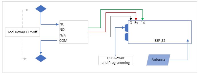
- Connect the relay to the pins 14, 5V, and G pins with the black wire oriented towards G. The relay on/off output is pin 14.
- The default behavior is NORMALLY OPEN. To change to NORMALLY CLOSE behavior you must apply a jumper/short to pin 8 to a G pin.
- The pins for the ON/OFF state for a stack light is pin 12. The pin for the DOWN/NOT DOWN state for the stack light is pin 13. This must be used with additional DFRobot relays isolating the stack light from the ESP32. Use the 5V and G pin as needed.
- NEVER apply any device or connection to any pins not explicitly described.
- Insert your antenna into the bottom left of the enclosure or create a gap to line the antenna to an external mount. Wait until the rest of the hardware is in place or mostly in place to connect to the antenna to the connector next to the main chip.
- Insert your relay into the right half of the enclosure. There is no spacing supplied here for stack light relays.
- Gently push your ESP32 into the top left section.
- Slide on the lid and use a 1/4-20 if needed to secure the lid to the base
- If assembled correctly you should be able to easily connect to both USB ports, view the ESP32 LED and relay status LED, press both boot and reset buttons as needed with a narrow plastic rod or small screw driver and access the EAC relay screws.
- To power your device use a USB micro cable plugged into a 'phone charger' or computer attached to the left (UART) port. The right (USB) port is reserved for future development.
- Rated current for the relay is 10A in NO regime, 5A in NC regime. Do not exceed this load, and suggested load is not to exceed 8A/4A. The terminals from left to right on the relay are NC/NO/NOTUSED/COMMON
- Take care to properly terminate your wire into the relay terminals. Failure to do so risks damaging hardware or causing electric shock. An experienced or qualified technician should make these connections.
The following is in the contents of the _README_FIRST.txt file. Please read through all of these steps before proceeding.
- Download the installer package 'Setup Files' attached in the Related Media section of this page. Extract it in any directory.
- Plug in your device via USB using the UART (left) port.
- Go to the 'dist' directory and double-click the appropriate batch file (Windows users: install-Win.bat)
-
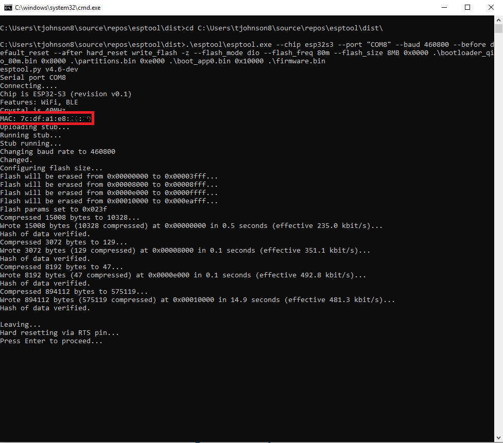
The .bat file will run the installer and report success or errors. Follow through the prompts. If you get a COM port does not exist try restarting your ESP32 a few times and re-running the .bat file. For other errors reach out to a developer or SUMS admin.
-
Please note your MAC Address. This is used to identify your device later as a EAC endpoint on SUMS. It is a twelve-character alphanumeric string with format XX:XX:XX:XX:XX:XX which gets written to the install terminal after connecting to the ESP32 device.
-
Once you get a progress notification of the upload you are looking for a final message of "Hard resetting via RTS pin...". You will get two prompts to end the installer and your device is ready to finish setup via smart phone.
-
Follow through the prompts. At this point you can re-run the installer if you are setting up multiple devices. Otherwise it will prompt you to register your device on Lawn (as described in Step 10).
-
Connect to the Wi-Fi server by going to your 'connect to network' on your phone. It should be similar to "ESP32_S3xxxxxx" in your Wi-Fi list. Go to your browser and put in the URL: 192.168.4.1
-
GO THROUGH THE WEB SETUP PROCESS DESCRIBED IN THE SECTION E BELOW. Finishing this process will disable the Wi-Fi server.
-
-
Once your device is registered you can configure further options by using the device's IP address.
-
Your device is ready to use by entering the MAC Address as the EAC endpoint on Tool Configuration for your given tool.
- Connect to the ESP32 Device Wi-Fi with your smart phone. The default security key is IENd3vDevice. Connection methods will vary based on your device. Use your default WiFi browser to connect. NOTE: Some WiFi connections may interrupt the setup if they have the "Auto-Join" function enabled, notably 'eduroam'. For best results go into the settings for your eduroam connection and temporarily toggle off "Auto-Join".
- Access the Web Setup by entering http://192.168.4.1 in a browser on your connected smart phone. Take care not to use saved URLs/characters in the URL from previous install. Your browser will often try to autocomplete the URL and this will pass parameters from previous installs to your current install.
- Enter the credentials for your Wi-Fi Network. Currently the only supported SSID is GTother (type: Wi-Fi PSK). You can get the Password for GTother here: https://portal.lawn.gatech.edu/key. Take care not to use incorrect characters or spaces. CASE SENSITIVE
- Use a descriptive and unique name for identifying the device later. We suggest esp32-SHORTNAMEFORDEPT-SHORTNAMEFORTOOL. For example an oven in the Pettit Cleanroom for IEN might be called esp32-IEN-pettitoven01
- Follow the optional setup for Microsoft Teams pings through sumBot. These can be noisy/annoying so they are generally for SUMS and lab admin who want to track the performance of their edge device portfolio.
- Check the checkmark if you are using a stack light assembly for visual status indication.
- Check your settings are correct and click Submit. If you missed noting your MAC Address it is also displayed on this page. Write it down!
- Confirm your settings, then click the EVERYTHING LOOKS GOOD link to disable the esp32 web server. If you mess up here, you will need to run the firmware installer again. The page will become unresponsive as your device switches over to your programmed Wi-Fi.
- The webserver will be disabled, and you can return to SECTION D:Step 11 above.
- Connect to your device using the IP address assigned on LAWN.
- Supply the configuration password if any. If there is a default password request it from a SUMS admin.
- The home page for your device will allow you to manually operate the outputs, change the build target from Stable to Nightly, and toggle the Stacklight functions.
- "Breathing" Blue - Active, Idle (This is the state you want your EDGE device to have)
- "Solid" Bright Blue - No MQTT comms
- "Solid" Green - MQTT verification
- "Blink" Purple - MQTT message/comms received
- "Solid" Yellow - Websocket (website) disconnected
- "Solid" Red - WiFi disconnected
- "Breathing" Yellow - Firmware updating
- "Breathing" Purple - Delayed Log Out
- "Solid" Other Colors - The ESP32 will often hold the last light color if it resets or crashes suddenly